Quick Summary: Fouling factor refers to the additional thermal resistance caused by scale, deposits, biological growth, or other buildup on a heat exchanger’s surfaces. As these layers accumulate, they interfere with heat transfer and gradually reduce the unit’s thermal performance. Different fouling mechanisms require different control methods, ranging from water chemistry management and appropriate flow velocities to upstream filtration and heat exchanger designs that promote turbulence. Routine inspections, chemical treatment, and planned cleaning can also limit buildup before it affects energy consumption or equipment reliability. Including a realistic fouling allowance during the initial design stage gives the exchanger enough capacity to maintain its required duty as deposits develop during service.
Anyone who specifies or maintains thermal equipment eventually runs into the term fouling factor, and understanding “What is fouling factor in heat exchanger performance?” is essential to keeping a system running at its rated capacity.
Fouling factor represents the additional thermal resistance created when deposits, scale, or biological growth build up on heat transfer surfaces, and it directly reduces how efficiently a unit moves heat between two fluids.
As the North American distributor for Spirec heat exchangers, Baron Blakeslee sees firsthand how design choices and maintenance habits affect fouling rates, and this guide covers both the concept and eleven ways to manage it.
Defining Fouling Factor
Fouling factor is expressed as an added thermal resistance value, in units of square meters times kelvin per watt, that engineers build into their design calculations to account for expected deposit buildup over the life of the equipment. A higher fouling factor means the exchanger needs more surface area up front to still hit its target performance once deposits accumulate.
Why Fouling Reduces Performance
Deposits form an insulating barrier between the process fluid and the heat transfer surface. Even a relatively thin layer can interfere with thermal exchange. As the buildup becomes more substantial, operators may need to increase flow rates or operating temperatures to maintain the required process conditions.
Those adjustments can increase energy consumption and place additional demands on pumps, heating systems, cooling equipment, and the exchanger itself. Persistent fouling can therefore affect both thermal efficiency and overall operating costs.
Common Fouling Mechanisms
Heat exchanger fouling generally develops through several mechanisms. Scaling occurs when dissolved minerals precipitate from a fluid and accumulate on heat transfer surfaces.
Particulate fouling results when suspended solids settle or adhere to internal surfaces. Biological fouling develops when microorganisms grow within the system, while chemical reaction fouling occurs when compounds react and form deposits, particularly under elevated temperatures.
Identifying the dominant fouling mechanism is important because each type responds to different prevention and cleaning methods. A strategy that works well against mineral scale may not address biological growth or particulate accumulation effectively.
How Fouling Factor is Calculated in Practice
Engineers can determine fouling resistance by comparing the heat transfer performance of a clean exchanger with its performance after a period of operation. The difference in thermal performance is translated into an additional resistance value that represents the effect of accumulated deposits.
Industry references also contain typical fouling factor ranges for common fluids and operating conditions. These values can serve as an initial design reference when site-specific operating data is not yet available. Actual field performance can then provide more precise information for future equipment sizing and maintenance planning.
The Cost of Ignoring Fouling
Uncontrolled fouling does more than reduce heat transfer efficiency. Operators may compensate for declining performance by increasing flow rates or temperatures, which raises energy consumption. Deposits can also contribute to corrosion beneath the buildup and shorten the time between necessary cleaning shutdowns.
A small decline in performance can therefore develop into a significant operating expense when fouling continues unchecked for months.
Identifying and addressing deposits earlier can reduce the likelihood of prolonged efficiency losses and unplanned maintenance.
How to Reduce Fouling in Heat Exchangers
1. Select Materials Suited to the Fluid Chemistry
Materials that are compatible with the process fluid can reduce corrosion, pitting, and surface deterioration that may contribute to deposit formation. Stainless steel and other corrosion-resistant alloys can maintain suitable heat transfer surfaces under demanding process conditions.
Material selection should account for chloride concentration, pH, temperature, pressure, and the presence of corrosive compounds. Matching exchanger construction to the fluid chemistry can address several potential sources of fouling while improving long-term durability.
2. Maintain Adequate Flow Velocity
Maintaining an appropriate flow velocity helps keep suspended particles moving through the exchanger instead of giving them an opportunity to settle on heat transfer surfaces.
Low velocities can produce stagnant areas where sediment and scale accumulate, while excessively high velocities may increase pressure drop and erosion.
Flow conditions should be evaluated alongside fluid viscosity, particle concentration, channel dimensions, and exchanger geometry. The goal is to establish a velocity range that limits deposits without introducing unnecessary pressure losses or material wear.
3. Use Compact, Turbulence-Promoting Designs
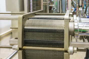
Corrugated and dimpled heat transfer surfaces can increase turbulence and improve fluid mixing throughout the exchanger. Greater turbulence reduces stagnant zones and makes it more difficult for particles or scale-forming compounds to remain attached to internal surfaces.
Compact exchanger designs can also achieve strong heat transfer rates within a relatively small footprint. Selecting an appropriate geometry requires consideration of thermal duty, pressure drop, installation constraints, and the specific fouling characteristics of the process fluid.
4. Control Water Chemistry
Water chemistry has a direct influence on mineral scale, corrosion products, and biological growth. Controlling parameters such as hardness, pH, alkalinity, dissolved oxygen, and contaminant concentration can reduce conditions that encourage deposit formation.
Treatment programs should reflect the water source, exchanger materials, operating temperatures, and process requirements. Regular testing can reveal changes in water chemistry early and help operators adjust treatment before deposits become difficult to control.
5. Schedule Regular Inspections
Routine inspections can identify developing fouling before deposits significantly reduce heat transfer performance. Operators can monitor temperature changes, pressure drop, flow conditions, and visible equipment conditions to identify deviations from normal operation.
Inspection frequency should reflect fluid characteristics, operating hours, temperature, and previous fouling history. Early detection allows maintenance teams to schedule cleaning during planned downtime.
6. Install Strainers or Filters Upstream
Upstream strainers and filters remove particles before they reach heat transfer surfaces. This helps reduce particulate fouling caused by sediment, debris, rust, and other suspended solids. The filtration system should match particle size, concentration, flow rate, and pressure requirements.
Operators should also monitor filter or strainer pressure drop because accumulated debris can restrict flow and negatively affect exchanger performance.
7. Apply Chemical Treatment Programs
Chemical treatment can control specific fouling mechanisms when selected for the process conditions. Anti-scalants can reduce mineral deposition, while biocides can control microorganisms responsible for biological fouling.
Treatment levels should account for fluid chemistry, temperature, exchanger materials, and operating conditions. Regular monitoring helps maintain appropriate dosing and reduces the risk of ineffective treatment or material damage.
8. Monitor Temperature Differentials
Monitoring inlet and outlet temperatures can reveal changes in heat exchanger performance caused by developing fouling. Deposits increase thermal resistance, reducing the exchanger’s ability to transfer heat effectively.
Operators can compare current readings with established clean-condition baselines and review them alongside flow rates and pressure drop. Consistent monitoring helps identify performance deterioration early and schedule maintenance appropriately.
9. Choose Gasket-Free, Welded Construction
Welded heat exchangers eliminate gasket interfaces within the heat transfer area, reducing crevices where deposits and microorganisms can accumulate. This construction can benefit applications involving aggressive fluids, demanding temperatures, or strict cleanliness requirements.
Weld quality and material selection remain important for long-term performance. For applications where crevice fouling is a concern, gasket-free construction can simplify maintenance and reduce potential accumulation points.
10. Clean on a Defined Schedule Rather Than Waiting for Failure
Waiting for noticeable performance loss can leave an exchanger operating inefficiently for an extended period. Establishing cleaning intervals based on operating history helps address deposits before they become difficult to remove.
Temperature performance, pressure drop, fluid quality, and previous cleaning results can guide scheduling. Proactive maintenance also allows cleaning to coincide with planned shutdowns, reducing operational disruption.
11. Size Equipment With Realistic Fouling Margins
Fouling should be considered during heat exchanger sizing to account for the thermal resistance created by deposits during operation. An appropriate fouling factor gives the exchanger sufficient heat transfer area to maintain its required duty as deposits develop.
Engineers should consider fluid chemistry, contaminant levels, temperatures, flow rates, and maintenance practices when establishing realistic allowances for long-term performance.
Working With Your Equipment Supplier On Fouling Data
Sharing accurate fluid analysis and expected operating conditions with your equipment supplier helps establish a realistic fouling factor during the specification stage. Details such as fluid composition, suspended solids, viscosity, operating temperatures, flow rates, pressure, and expected service conditions give engineers a clearer picture of how deposits could affect heat transfer over time.
Historical maintenance records can also reveal cleaning frequency and common fouling mechanisms from similar equipment or existing systems. With this information, the supplier can calculate an appropriate fouling allowance rather than relying on broad industry assumptions.
This helps balance heat transfer area, equipment size, pressure drop, and operating costs while reducing the risk of selecting a unit that is undersized or unnecessarily oversized for the intended application and long-term service conditions.
Choose the Right Heat Exchanger for Fouling Control
Preventing fouling is far less expensive than living with reduced efficiency or emergency cleaning downtime, and equipment selection plays a large role in how well a system resists deposits over its service life.
Baron Blakeslee’s Spirec heat exchangers use a welded, single-pass design specifically chosen to limit the conditions that lead to fouling, and our technical data resources detail flow velocities and surface areas for each model.
If your facility is also managing surface preparation ahead of coating operations, keeping upstream equipment clean plays a direct role in downstream product quality as well.
Speak with our team about sizing an exchanger with the right fouling margin for your process.
Frequently Asked Questions
How is fouling factor different from overall heat transfer coefficient?
Overall heat transfer coefficient describes how efficiently a clean exchanger moves heat, while fouling factor is the added resistance engineers account for once deposits begin forming over time.
Can fouling factor be reduced to zero through good design?
No, some fouling is expected over the operating life of nearly any exchanger, but design choices and maintenance practices can meaningfully slow how quickly it builds up.
What are early warning signs of fouling in a heat exchanger?
A gradually widening gap between the expected and actual outlet temperature, along with rising pressure drop across the unit, often indicates that deposits are starting to affect performance.
Does cylindrical-plate technology foul less than shell-and-tube designs?
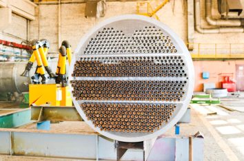
The dimpled plate surface promotes turbulence that helps keep the unit self-cleaning, which tends to slow fouling compared with the lower-velocity zones found in some shell-and-tube configurations.
How often should a heat exchanger be cleaned to manage fouling?
Cleaning frequency depends on the fluid and application, but scheduling inspections at defined intervals rather than waiting for a performance drop tends to keep costs and downtime lower.